lecture7
지식붕괴의 시대, 세종의 공부법 “질문하고 토론하라”
HW3
Lab4-GeometryPositionColorComposeAnimation 에서 제공하는 클래스를 이용하여, 본인이 원하는 3차원 객체를 2~3개 만들어서 하나의 장면(예: 본인 이름 등)을 만든다. 그리고 catmull-rom curve를 이용하여 animation의 움직임을 넣는다. (Due by 10/12) (10점)
-your 3D geometry (eg. your name, spaceship, etc) 를 만들어서 장면을 완성하고 움직임을 추가
glm::transform
glm::mat4 T = glm::translate(glm::mat4(1.0f), glm::vec3(dx, dy, dz));
![]()
glm::mat4 R = glm::rotate(glm::mat4(1.0f), theta, glm::vec3(ax, ay, az));
glm::mat4 S = glm::scale(glm::mat4(1.0f), glm::vec3(sx, sy, sz));
glm::mat4 Tx = glm::translate(glm::mat4(1.0f), glm::vec3(3.0f, 0.0f, 0.0f));
glm::mat4 Rz = glm::rotate(glm::mat4(1.0f), 45.0f, glm::vec3(0.0f, 0.0f, 1.0f));
glm::mat4 S = glm::scale(glm::mat4(1.0f), glm::vec3(0.5f, 0.7f, 1.0f));
glm::mat4 TRS = Tx * Rz * S; // Scale XY, and then Rotate Z, and then Translate X
위의 코드는 아래의 코드와 동일한 행렬의 곱 연산을 수행한다.
glm::mat4 T = glm::translate(glm::mat4(1.0f), glm::vec3(3.0f, 0.0f, 0.0f)); // T
glm::mat4 TR = glm::rotate(T, 45.0f, glm::vec3(0.0f, 0.0f, 1.0f)); // T * R
glm::mat4 TRS = glm::scale(TR, glm::vec3(0.5f, 0.7f, 1.0f)); // T * R * S
GeometryPositionColorComposeTransformation
lab6-GeometryPositionColorComposeTransformation
// MVP matrix
Projection = glm::perspective(g_fovy, g_aspect, g_zNear, g_zFar);
View = glm::lookAt(g_eye, g_at, g_up);
spMain.useProgram();
spMain.setUniform(“gProjection”, Projection);
spMain.setUniform(“gView”, View);
// p’ = M3 * M2 * M1 * p (OpenGL uses Column-Major Order)
glm::mat4 Tx = glm::translate(glm::mat4(1.0f), glm::vec3(3.0f, 0.0f, 0.0f)); // RHS x+ right
glm::mat4 Rz = glm::rotate(glm::mat4(1.0f), 45.0f, glm::vec3(0.0f, 0.0f, 1.0f)); // RHS z+ (X->Y rotation)
glm::mat4 S = glm::scale(glm::mat4(1.0f), glm::vec3(2.0f, 2.0f, 2.0f)); // RHS
World = glm::mat4(1.0f);
spMain.setUniform(“gModel”, World);
cube1->draw();
// p’= R T p (red) => translate, and then rotate
glm::mat4 RT = Rz * Tx;
World = RT;
spMain.setUniform(“gModel”, World);
cube2->draw();
// p’= T R p (green) => rotate, and then translate
glm::mat4 TR = Tx * Rz;
World = TR;
spMain.setUniform(“gModel”, World);
cube3->draw();
// p’= T R S p (blue) => scale, and then rotate, and then translate
glm::mat4 TRS = Tx * Rz * S;
World = TRS;
spMain.setUniform(“gModel”, World);
cube4->draw();
// p’= S R T p (blue) => translate, and then rotate, and then scale
glm::mat4 SRT = S * Rz * Tx;
World = SRT;
spMain.setUniform(“gModel”, World);
cube4->draw();
![]()
OPENGL TRANSFORMATION MATRIX TUTORIAL
http://www.opengl-tutorial.org/beginners-tutorials/tutorial-3-matrices/
Homogeneous coordinates
Until then, we only considered 3D vertices as a (x,y,z) triplet. Let’s introduce w. We will now have (x,y,z,w) vectors.
This will be more clear soon, but for now, just remember this :
- If w == 1, then the vector (x,y,z,1) is a position in space.
- If w == 0, then the vector (x,y,z,0) is a direction.
(In fact, remember this forever.)
What difference does this make ? Well, for a rotation, it doesn’t change anything. When you rotate a point or a direction, you get the same result. However, for a translation (when you move the point in a certain direction), things are different. What could mean “translate a direction” ? Not much.Homogeneous coordinates allow us to use a single mathematical formula to deal with these two cases.
Transformation matrices
In 3D graphics we will mostly use 4×4 matrices. They will allow us to transform our (x,y,z,w) vertices. This is done by multiplying the vertex with the matrix :
Matrix x Vertex (in this order !!) = TransformedVertex
In C++, with GLM:
glm::mat4 myMatrix;
glm::vec4 myVector;
// fill myMatrix and myVector somehow
glm::vec4 transformedVector = myMatrix * myVector; // Again, in this order ! this is important.
In GLSL :
mat4 myMatrix;
vec4 myVector;
// fill myMatrix and myVector somehow
vec4 transformedVector = myMatrix * myVector; // Yeah, it's pretty much the same than GLM
Translation matrices
These are the most simple tranformation matrices to understand. A translation matrix look like this :
![]()
where X,Y,Z are the values that you want to add to your position.
So if we want to translate the vector (10,10,10,1) of 10 units in the X direction, we get :
![]()
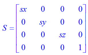
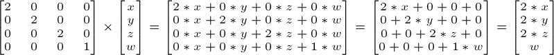
Scaling matrices
Scaling matrices are quite easy too :

So if you want to scale a vector (position or direction, it doesn’t matter) by 2.0 in all directions :
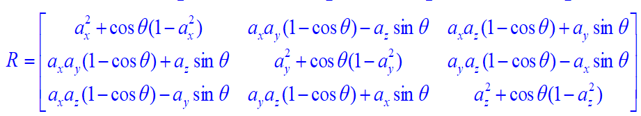
Rotation matrices
These are quite complicated.
Cumulating transformations
So now we know how to rotate, translate, and scale our vectors. It would be great to combine these transformations. This is done by multiplying the matrices together, for instance :
TransformedVector = TranslationMatrix * RotationMatrix * ScaleMatrix * OriginalVector;
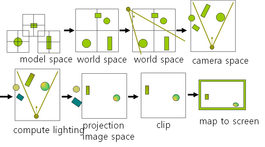
The Model, View and Projection matrices
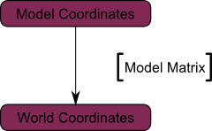
The Model matrix
This model, just as our beloved red triangle, is defined by a set of vertices. The X,Y,Z coordinates of these vertices are defined relative to the object’s center : that is, if a vertex is at (0,0,0), it is at the center of the object.
We can sum this up with the following diagram :
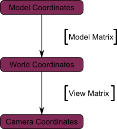
The View matrix
We went from World Space (all vertices defined relatively to the center of the world, as we made so in the previous section) to Camera Space (all vertices defined relatively to the camera).
Here’s the compulsory diagram :
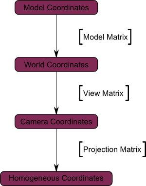
The Projection matrix
We’re now in Camera Space. This means that after all theses transformations, a vertex that happens to have x==0 and y==0 should be rendered at the center of the screen.
And the final diagram :
OPENGL/GLM TRANSFORMATION (COLUMN-MAJOR ORDER)
glm::mat4 A(1.0f, 0.0f, 0.0f, 0.0f, // column1
0.0f, 2.0f, 0.0f, 0.0f, // column2
0.0f, 0.0f, 4.0f, 0.0f, // column3
1.0f, 2.0f, 3.0f, 1.0f); // column4
// A =
// 1 0 0 1
// 0 2 0 2
// 0 0 4 3
// 0 0 0 1
glm::mat4 B(1.0f, 0.0f, 0.0f, 0.0f, // column1
0.0f, 1.0f, 0.0f, 0.0f, // column2
0.0f, 0.0f, 1.0f, 0.0f, // column3
2.0f, 2.0f, 2.0f, 1.0f); // column4
// B =
// 1 0 0 2
// 0 1 0 2
// 0 0 1 2
// 0 0 0 1
glm::mat4 C = A*B;
// C = A*B =
// 1 0 0 3
// 0 2 0 6
// 0 0 4 11
// 0 0 0 1
glm::mat4 D = B*A;
// D = B*A =
// 1 0 0 3
// 0 2 0 4
// 0 0 4 5
// 0 0 0 1
glm::mat4 E = glm::inverse(A); // inverse
// E = inverse(A) =
// 1 0 0 -1
// 0 0.5 0 -1
// 0 0 0.25 -0.75
// 0 0 0 1
glm::mat4 I = A * E; // I = A * A-1
// I = A*E =
// 1 0 0 0
// 0 1 0 0
// 0 0 1 0
// 0 0 0 1
// p’ = M * p (OpenGL/GLM uses Column-Major Order)
glm::vec4 p = glm::vec4(1.0f, 0.0f, 0.0f, 1.0f);
// p = (1, 0, 0)
glm::vec4 q = A * p;
// q = A * p = (2, 2, 3)
glm::vec4 r = B * p;
// r = B * p = (3, 2, 2)
glm::vec4 s = C * p;
// s = A * B * p = (4, 6, 11)
glm::vec4 t = D * p;
// t = B * A * p = (4, 4, 5)
glm::mat4 Tx,Ty,Tz;
Tx = glm::translate(glm::mat4(1.0f), glm::vec3(2.0f, 0.0f, 0.0f)); // RHS x+ right
Ty = glm::translate(glm::mat4(1.0f), glm::vec3(0.0f, 2.0f, 0.0f)); // RHS y+ up
Tz = glm::translate(glm::mat4(1.0f), glm::vec3(0.0f, 0.0f, 2.0f)); // RHS z+ front
// Tx =
// 1 0 0 2
// 0 1 0 0
// 0 0 1 0
// 0 0 0 1
// Ty =
// 1 0 0 0
// 0 1 0 2
// 0 0 1 0
// 0 0 0 1
// Tz =
// 1 0 0 0
// 0 1 0 0
// 0 0 1 2
// 0 0 0 1
glm::mat4 Rx,Ry,Rz,Ra;
Rx = glm::rotate(glm::mat4(1.0f), 30.0f, glm::vec3(1.0f, 0.0f, 0.0f)); // RHS x+ (Y->Z rotation) OpenGL uses DEGREE angle
Ry = glm::rotate(glm::mat4(1.0f), 60.0f, glm::vec3(0.0f, 1.0f, 0.0f)); // RHS y+ (Z->X rotation)
Rz = glm::rotate(glm::mat4(1.0f), 45.0f, glm::vec3(0.0f, 0.0f, 1.0f)); // RHS z+ (X->Y rotation)
Ra = glm::rotate(glm::mat4(1.0f), 45.0f, glm::vec3(1.0f, 1.0f, 1.0f)); // RHS (arbitrary axis)
// Rx =
// 1 0 0 0
// 0 0.999958 -0.0091384 0
// 0 0.0091384 0.999958 0
// 0 0 0 1
// Ry =
// 0.999833 0 0.018276 0
// 0 1 0 0
// -0.018276 0 0.999833 0
// 0 0 0 1
// Rz =
// 0.999906 -0.0137074 0 0
// 0.0137074 0.999906 0 0
// 0 0 1 0
// 0 0 0 1
// Ra =
// 0.999937 -0.00788263 0.00794526 0
// 0.00794526 0.999937 -0.00788263 0
// -0.00788263 0.00794526 0.999937 0
// 0 0 0 1
glm::mat4 Sx,Sy,Sz;
Sx = glm::scale(glm::mat4(1.0f), glm::vec3(2, 1, 1)); // RHS
Sy = glm::scale(glm::mat4(1.0f), glm::vec3(1, 2, 1)); // RHS
Sz = glm::scale(glm::mat4(1.0f), glm::vec3(1, 1, 2)); // RHS
// Sy =
// 1 0 0 0
// 0 2 0 0
// 0 0 1 0
// 0 0 0 1
// p’ = M3 * M2 * M1 * p (OpenGL uses Column-Major Order)
glm::mat4 TR = Tx * Rz; // Rotate Z, and then Translate X
glm::mat4 RT = Rz * Tx; // Translate X, and then Rotate Z
glm::mat4 TRS = Tx * Rz * Sy; // Scale Y, and then Rotate Z, and then Translate X
glm::mat4 SRT = Sy * Rz * Tx; // Translate X, and then Rotate Z, and then Scale Y
// Tx*Rz =
// 0.707107 -0.707107 0 2
// 0.707107 0.707107 0 0
// 0 0 1 0
// 0 0 0 1
// Rz*Tx =
// 0.707107 -0.707107 0 1.41421
// 0.707107 0.707107 0 1.41421
// 0 0 1 0
// 0 0 0 1
// Tx*Rz*Sy =
// 0.707107 -1.41421 0 2
// 0.707107 1.41421 0 0
// 0 0 1 0
// 0 0 0 1
// Sy*Rz*Tx =
// 0.707107 -0.707107 0 1.41421
// 1.41421 1.41421 0 2.82843
// 0 0 1 0
// 0 0 0 1
GLM MATRIX (COLUMN-MAJOR ORDER)
int foo()
{
glm::vec4 Position = glm::vec4(glm:: vec3(0.0f), 1.0f);
glm::mat4 Model = glm::translate(glm::mat4(1.0f), glm::vec3(1.0f, 2.0f, 3.0f));
// (1.0, 0.0, 0.0, 1.0)
// (0.0, 1.0, 0.0, 2.0)
// (0.0, 0.0, 1.0, 3.0)
// (0.0, 0.0, 0.0, 1.0)
printf(“%f %f %f %f\n”, Model[0][0], Model[1][0], Model[2][0], Model[3][0]);
printf(“%f %f %f %f\n”, Model[0][1], Model[1][1], Model[2][1], Model[3][1]);
printf(“%f %f %f %f\n”, Model[0][2], Model[1][2], Model[2][2], Model[3][2]);
printf(“%f %f %f %f\n”, Model[0][3], Model[1][3], Model[2][3], Model[3][3]);
glm::vec4 Transformed = Model * Position; // P’ (1, 2, 3) = Model * P (0, 0, 0) (OpenGL uses Column-Major Order) RHS
…
return 0;
}
Vector Matrix Plane
Vector Matrix Plane using glm
void mprint(glm::mat4& Mat)
{
printf(“\n %f %f %f %f\n %f %f %f %f\n %f %f %f %f\n %f %f %f %f\n\n”,
Mat[0][0], Mat[1][0], Mat[2][0], Mat[3][0],
Mat[0][1], Mat[1][1], Mat[2][1], Mat[3][1],
Mat[0][2], Mat[1][2], Mat[2][2], Mat[3][2],
Mat[0][3], Mat[1][3], Mat[2][3], Mat[3][3]);
}
float theta(const glm::vec3& v1, const glm::vec3& v2)
{
float len1 = (float)sqrtf(v1[0]*v1[0] + v1[1]*v1[1] + v1[2]*v1[2]);
float len2 = (float)sqrtf(v2[0]*v2[0] + v2[1]*v2[1] + v2[2]*v2[2]);
return (float)acosf(dot(v1, v2)/len1*len2);
}
glm::vec3 computeNormal(glm::vec3& a, glm::vec3& b, glm::vec3& c)
{
glm::vec3 normal = glm::normalize(glm::cross(c – a, b – a));
return normal;
}
void vec3Test()
{
const float v[3] = { 1.0f, 2.0f, 3.0f };
vec3 a(0.0f, 0.0f, 0.0f), b(1.0f, 2.0f, 3.0f), c(b);
vec3 d = c;
vec3 e = c;
vec3 f = a;
cout << “a = ” << a[0] << ” ” << a[1] << ” ” << a[2] << endl;
cout << “b = ” << b[0] << ” ” << b[1] << ” ” << b[2] << endl;
cout << “c = ” << c[0] << ” ” << c[1] << ” ” << c[2] << endl;
cout << “d = ” << d[0] << ” ” << d[1] << ” ” << d[2] << endl;
cout << “e = ” << e[0] << ” ” << e[1] << ” ” << e[2] << endl;
a[0] = 4;
a[1] = 5;
a[2] = 6;
cout << “after assignments, a (4,5,6) ” << endl;
cout << “a = ” << a[0] << ” ” << a[1] << ” ” << a[2] << endl;
cout << “b = ” << b[0] << ” ” << b[1] << ” ” << b[2] << endl;
cout << “Unary Operation” << endl;
a += b;
cout << “a += b ” << endl;
cout << “a = ” << a[0] << ” ” << a[1] << ” ” << a[2] << endl;
a -= b;
cout << “a -= b ” << endl;
cout << “a = ” << a[0] << ” ” << a[1] << ” ” << a[2] << endl;
a *= 1.5;
cout << “a *= 1.5 ” << endl;
cout << “a = ” << a[0] << ” ” << a[1] << ” ” << a[2] << endl;
a /= 1.5;
cout << “a /= 1.5 ” << endl;
cout << “a = ” << a[0] << ” ” << a[1] << ” ” << a[2] << endl;
cout << “Binary Operation” << endl;
c = a + b;
cout << “c = a + b -> c ” << endl;
cout << “c = ” << c[0] << ” ” << c[1] << ” ” << c[2] << endl;
c = a – b;
cout << “c = a – b -> c ” << endl;
cout << “c = ” << c[0] << ” ” << c[1] << ” ” << c[2] << endl;
cout << “a == b” << endl;
if (a == b)
cout << ” is true” << endl;
else
cout << ” is false” << endl;
cout << “b == d” << endl;
if (b == d)
cout << ” is true” << endl;
else
cout << ” is false” << endl;
// magnitude
cout << “a = ” << a[0] << ” ” << a[1] << ” ” << a[2] << endl;
cout << “b = ” << b[0] << ” ” << b[1] << ” ” << b[2] << endl;
cout << “a magnitude = ” << (float)sqrt(a[0]*a[0] + a[1]*a[1] + a[2]*a[2]) << endl;
cout << “b magnitude = ” << (float)sqrt(b[0]*b[0] + b[1]*b[1] + b[2]*b[2]) << endl;
// normalize
c = normalize(a);
cout << “c = normalize(a) = ” << c[0] << ” ” << c[1] << ” ” << c[2] << endl;
cout << “c magnitude = ” << (float)sqrt(c[0]*c[0] + c[1]*c[1] + c[2]*c[2]) << endl;
d = normalize(b);
cout << “d = normalize(b) = ” << d[0] << ” ” << d[1] << ” ” << d[2] << endl;
cout << “d magnitude = ” << (float)sqrt(d[0]*d[0] + d[1]*d[1] + d[2]*d[2]) << endl;
// dot product, theta, cross product, compute normal
cout << “dot(a, b) = ” << dot(a, b) << endl;
cout << “a,b angle = ” << degrees(theta(a, b)) << endl;
e = cross(a, b);
cout << “e = cross(a, b) = ” << e[0] << ” ” << e[1] << ” ” << e[2] << endl;
f = cross(vec3(1.0f, 3.0f, -4.0f), vec3(2.0f, -5.0f, 8.0f));
cout << “(1, 3, -4) x (2, -5, 8) = ” << f[0] << ” ” << f[1] << ” ” << f[2] << endl;
glm::vec3 g = computeNormal(glm::vec3(1.0f, 0.0f, 0.0f), glm::vec3(1.0f, 1.0f, 0.0f), glm::vec3(1.0f, 2.0f, 3.0f));
cout << “g = ” << g[0] << ” ” << g[1] << ” ” << g[2] << endl;
}
void mat4Test()
{
// matrix test
glm::mat4 M(1.0f, 2.0f, 3.0f, 4.0f, // column1
5.0f, 6.0f, 7.0f, 8.0f, // column2
9.0f, 10.0f, 11.0f, 12.0f, // column3
13.0f, 14.0f, 15.0f, 16.0f); // column4
cout << “M = ” << endl;
mprint(M);
glm::mat4 A(1.0f, 0.0f, 0.0f, 0.0f, // column1
0.0f, 2.0f, 0.0f, 0.0f, // column2
0.0f, 0.0f, 4.0f, 0.0f, // column3
1.0f, 2.0f, 3.0f, 1.0f); // column4
cout << “A = ” << endl;
mprint(A);
glm::mat4 B(1.0f, 0.0f, 0.0f, 0.0f, // column1
0.0f, 1.0f, 0.0f, 0.0f, // column2
0.0f, 0.0f, 1.0f, 0.0f, // column3
2.0f, 2.0f, 2.0f, 1.0f); // column4
cout << “B = ” << endl;
mprint(B);
glm::mat4 C = A * B; // multiplication
cout << “C = A*B = ” << endl;
mprint(C);
glm::mat4 D = B * A; // multiplication
cout << “D = B*A = ” << endl;
mprint(D);
glm::mat4 E = glm::inverse(A); // inverse
cout << “E = inverse(A) = ” << endl;
mprint(E);
glm::mat4 I = A * E; // multiplication
cout << “I = A*E = ” << endl;
mprint(I);
glm::vec4 p = glm::vec4(1.0f, 0.0f, 0.0f, 1.0f);
glm::vec4 q = A * p;
glm::vec4 r = B * p;
glm::vec4 s = C * p;
glm::vec4 t = D * p;
cout << “q = A*p = ” << endl;
printf(“(1, 0, 0, 1) => (%f, %f, %f, %f)\n”, q[0], q[1], q[2], q[3]);
cout << “r = B*p = ” << endl;
printf(“(1, 0, 0, 1) => (%f, %f, %f, %f)\n”, r[0], r[1], r[2], r[3]);
cout << “s = A*B*p = ” << endl;
printf(“(1, 0, 0, 1) => (%f, %f, %f, %f)\n”, s[0], s[1], s[2], s[3]);
cout << “t = B*A*p = ” << endl;
printf(“(1, 0, 0, 1) => (%f, %f, %f, %f)\n”, t[0], t[1], t[2], t[3]);
glm::mat4 Tx, Ty, Tz;
Tx = glm::translate(glm::mat4(1.0f), glm::vec3(2.0f, 0.0f, 0.0f)); // RHS x+ right
Ty = glm::translate(glm::mat4(1.0f), glm::vec3(0.0f, 2.0f, 0.0f)); // RHS y+ up
Tz = glm::translate(glm::mat4(1.0f), glm::vec3(0.0f, 0.0f, 2.0f)); // RHS z+ front
printf(“Tx\n”);
mprint(Tx);
glm::vec4 Position = glm::vec4(1.0f, 0.0f, 0.0f, 1.0f);
glm::vec4 tV = Tx * Position;
printf(“(1, 0, 0, 1) => (%f, %f, %f, %f)\n”, tV[0], tV[1], tV[2], tV[3]);
glm::mat4 Rx, Ry, Rz, Ra;
Rx = glm::rotate(glm::mat4(1.0f), 30.0f, glm::vec3(1.0f, 0.0f, 0.0f));
Ry = glm::rotate(glm::mat4(1.0f), 60.0f, glm::vec3(0.0f, 1.0f, 0.0f));
Rz = glm::rotate(glm::mat4(1.0f), 45.0f, glm::vec3(0.0f, 0.0f, 1.0f));
Ra = glm::rotate(glm::mat4(1.0f), 45.0f, glm::vec3(1.0f, 1.0f, 1.0f));
printf(“R\n”);
mprint(Rx);
mprint(Ry);
mprint(Rz);
mprint(Ra);
glm::vec4 tV1 = Ra * Position;
printf(“Ra * Position(1, 0, 0, 1) => (%f, %f, %f, %f)\n”, tV1[0], tV1[1], tV1[2], tV1[3]);
glm::mat4 Sx, Sy, Sz;
Sx = glm::scale(glm::mat4(1.0f), glm::vec3(2, 1, 1));
Sy = glm::scale(glm::mat4(1.0f), glm::vec3(1, 2, 1));
Sz = glm::scale(glm::mat4(1.0f), glm::vec3(1, 1, 2));
printf(“Sy\n”);
mprint(Sy);
glm::vec4 tV2 = Sy * Position;
printf(“(1, 0, 0, 1) => (%f, %f, %f, %f)\n”, tV2[0], tV2[1], tV2[2], tV2[3]);
glm::mat4 TR = Tx * Rz; // Rotate Z and then Translate X
printf(“TR\n”);
mprint(TR);
glm::vec4 tV3 = TR * Position;
printf(“(1, 0, 0, 1) => (%f, %f, %f, %f)\n”, tV3[0], tV3[1], tV3[2], tV3[3]);
mat4 RT = Rz * Tx; // Translate X and then Rotate Z
printf(“RT\n”);
mprint(RT);
glm::vec4 tV4 = RT * Position;
printf(“(1, 0, 0, 1) => (%f, %f, %f, %f)\n”, tV4[0], tV4[1], tV4[2], tV4[3]);
}
void matrix4x4Test()
{
// matrix test
matrix4x4 A(1.0f, 0.0f, 0.0f, 1.0f,
0.0f, 2.0f, 0.0f, 2.0f,
0.0f, 0.0f, 4.0f, 3.0f,
0.0f, 0.0f, 0.0f, 1.0f);
matrix4x4 B(1.0f, 0.0f, 0.0f, 2.0f,
0.0f, 1.0f, 0.0f, 2.0f,
0.0f, 0.0f, 1.0f, 2.0f,
0.0f, 0.0f, 0.0f, 1.0f);
matrix4x4 C = A * B; // multiplication
matrix4x4 D = B * A; // multiplication
float det = A.determinant(); // determinant
matrix4x4 E = A.inverse(); // inverse
matrix4x4 F = A * E; // multiplication
vector3 p(1.0f, 0.0f, 0.0f);
vector3 q = A * p;
vector3 r = B * p;
vector3 s = C * p;
vector3 t = D * p;
cout << “A = ” << endl << A << endl;
cout << “B = ” << endl << B << endl;
cout << “C = A*B = ” << endl << C << endl;
cout << “D = B*A = ” << endl << D << endl;
cout << “E = inverse(A) = ” << endl << E << endl;
cout << “det = determinant(A) = ” << endl << det << endl;
cout << “F = A*E = ” << endl << F << endl;
cout << “p = ” << p << endl;
cout << “q = A * p = ” << q << endl;
cout << “r = B * p = ” << r << endl;
cout << “s = A * B * p = ” << s << endl;
cout << “t = B * A * p = ” << t << endl;
matrix4x4 Tx, Ty, Tz;
Tx.translate(2.0f, 0.0f, 0.0f); // RHS x+ right
Ty.translate(0.0f, 2.0f, 0.0f); // RHS y+ up
Tz.translate(0.0f, 0.0f, 2.0f); // RHS z+ front
vector3 Position(1.0f, 0.0f, 0.0f);
vector3 tV = Tx * Position;
printf(“Tx*P = (1, 0, 0, 1) => (%f, %f, %f)\n”, tV[0], tV[1], tV[2]);
matrix4x4 Rx, Ry, Rz, Ra;
Rx.rotate(30.0f, ‘x’);
Ry.rotate(60.0f, ‘y’);
Rz.rotate(45.0f, ‘z’);
Ra.rotate(45.0f, 1.0f, 1.0f, 1.0f);
matrix4x4 Sx, Sy, Sz;
Sx.scale(2, 1, 1);
Sy.scale(1, 2, 1);
Sz.scale(1, 1, 2);
cout << “Tx = ” << endl << Tx << endl;
cout << “Rx = ” << endl << Rx << endl;
cout << “Ry = ” << endl << Ry << endl;
cout << “Rz = ” << endl << Rz << endl;
cout << “Ra = ” << endl << Ra << endl;
cout << “Sy = ” << endl << Sy << endl;
cout << “Tx*Rz = ” << endl << Tx*Rz << endl; // Rotate Z, and then Translate X
cout << “Rz*Tx = ” << endl << Rz*Tx << endl; // Translate X, and then Rotate Z
cout << “Tx*Rz*Sy = ” << endl << Tx*Rz*Sy << endl; // Scale Y, and then Rotate Z, and then Translate X
cout << “Sy*Rz*Tx = ” << endl << Sy*Rz*Tx << endl; // Translate X, and then Rotate Z, and then Scale Y
vector3 tV1 = Ra * Position;
printf(“Ra*P = (1, 0, 0, 1) => (%f, %f, %f)\n”, tV1[0], tV1[1], tV1[2]);
}
typedef struct _RAY {
vector3 p; // start point
vector3 u; // direction
} RAY;
bool RayPlaneIntersection(oglclass::plane p, RAY l, vector3& out)
{
float denom = plane::dotNormal(p, l.u); // dotNormal = a.x + b*y + c*z
//cout << “denom = ” << denom << endl;
if (denom == 0)
return false;
float t = -plane::dotCoord(p, l.p)/denom; // dotCoord = a*x + b*y + c*z + d*1
//cout << “t = ” << t << endl; // [0, -1, 0]
if (t < 0)
return false;
out = l.p + t*(l.u); // return vector
return true;
}
void planeTest()
{
// RAY-plane intersection test
plane plane0(1, 0, 0, 1);
cout << “plane0 = ” << plane0 << endl;
vector3 Q(2, 1, -1), P(-1, 1, 0);
int ret = plane::isPointInsideOutside(plane0, Q);
cout << “ret = ” << ret << endl; // ret = 1 (outside the plane)
ret = plane::isPointInsideOutside(plane0, P);
cout << “ret = ” << ret << endl; // ret = 0 (on the plane)
P = plane::closestPointOnPlane(plane0, Q);
cout << “P = ” << P << endl; // P = (-1, 1, -1)
RAY ray1, ray2, ray3;
ray1.p = vector3(1, 0, 0);
ray1.u = vector3(-1, -1, 0);
ray2.p = vector3(1, 0, -2);
ray2.u = vector3(1, 1, 1);
ray3.p = vector3(1, 1, 0);
ray3.u = vector3(1, 1, 1);
vector3 out1, out2, out3;
if (RayPlaneIntersection(plane0, ray1, out1))
cout << “out1 = ” << out1 << endl; // out1=(-1, -2, 0)
if (RayPlaneIntersection(plane0, ray2, out2))
cout << “out2 = ” << out2 << endl; // nothing
if (RayPlaneIntersection(plane0, ray3, out3))
cout << “out3 = ” << out3 << endl; // nothing
}
Coordinate System